Model Selection Table
Specifications
| Orifice Size [mm] |
φ7 equivalency |
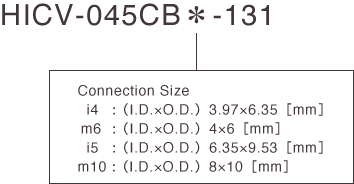
| Connection Size [mm] |
3.97×6.35 |
4×6 |
6.35×9.53 |
8×10 |
Recommended Flow Range
[L/min]H2O |
0.4 ~ 2 |
1 ~ 5 |
| Media Pressure |
Inlet
Pressure
[MPa] |
0 ~ 0.5 |
Outlet
Pressure
[MPa] |
0 ~ 0.5 |
| Media |
DI water / Corrosive fluid (Do not use fluids which can attack wetted materials) |
| Media Temperature [℃] |
10 ~ 90 |
| Ambient Temperature [℃] |
0 ~ 40 |
| Pneumatic Pressure [MPa] |
0.1 ~ 0.3 |
| Wetted Material |
Corrosion-resistant plastic |
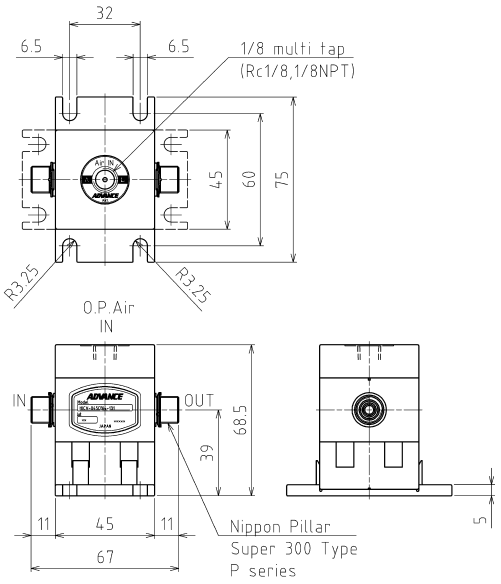
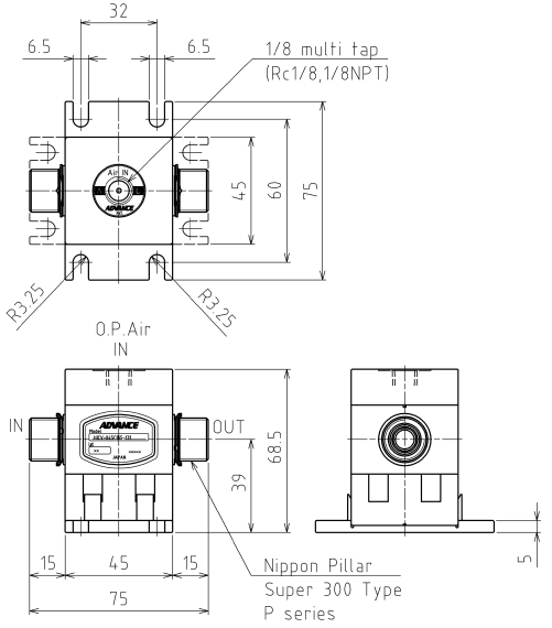
Dimensional Drawing(unit : mm)
HICV-045CB*-131 (Connection Size : 3.97×6.35, 4×6)
HICV-045CB*-131 (Connection Size : 6.35×9.53, 8×10)
HICV-045CB*-131 (Connection Size : 3.97×6.35, 4×6)
-
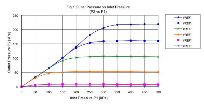
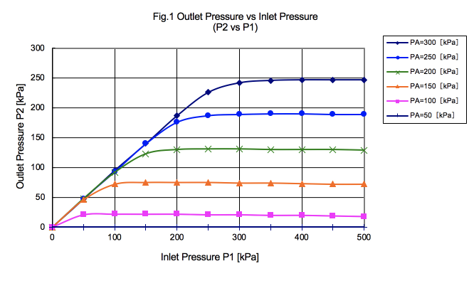
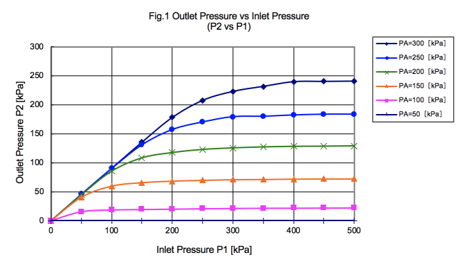
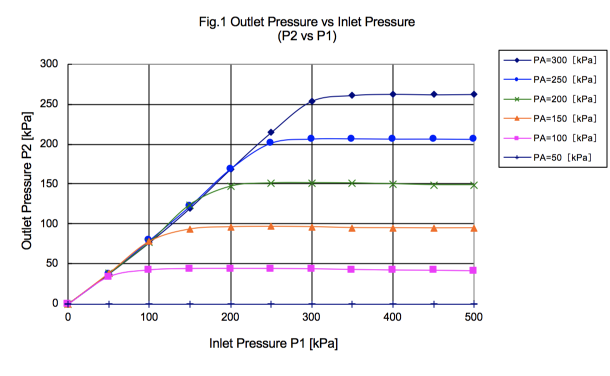
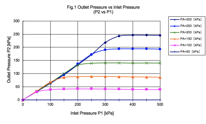
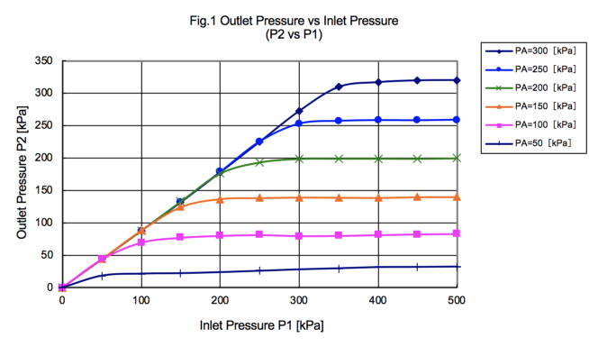
Fig. 1 Outlet Pressure vs Inlet Pressure
Measurement Method :
1.5mm fixed orifice is installed down stream of test unit.
-
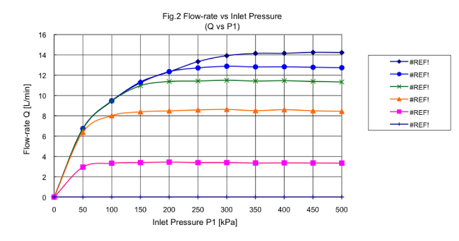
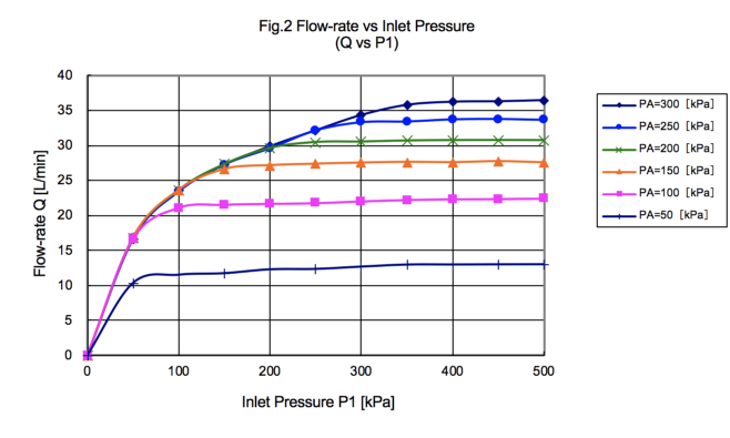
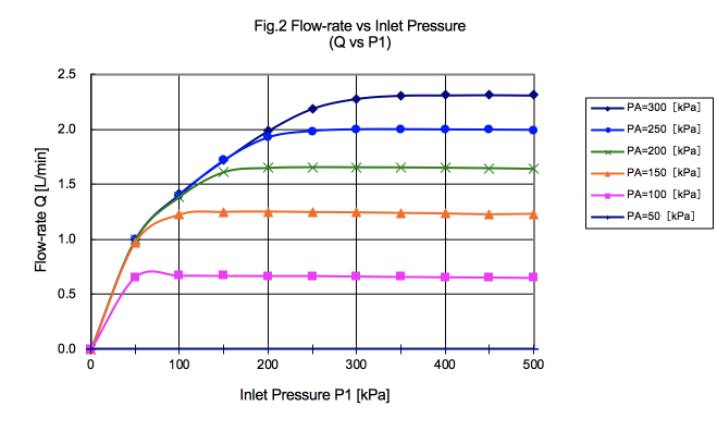
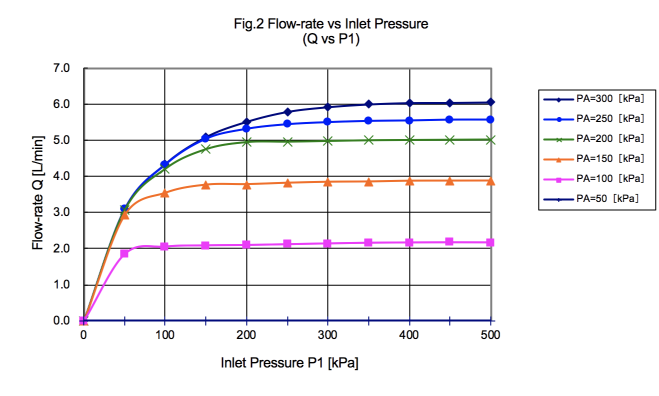
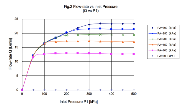
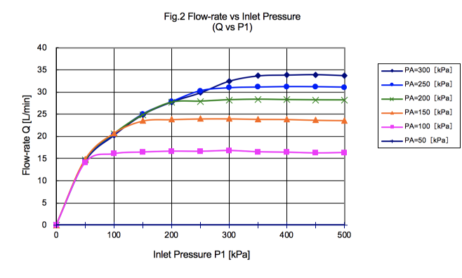
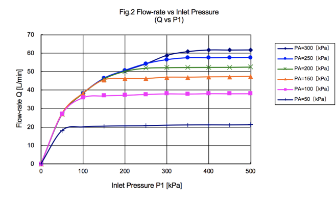
Fig. 2 Flow-rate vs Inlet Pressure
Measurement Method :
1.5mm fixed orifice is installed down stream of test unit.
-
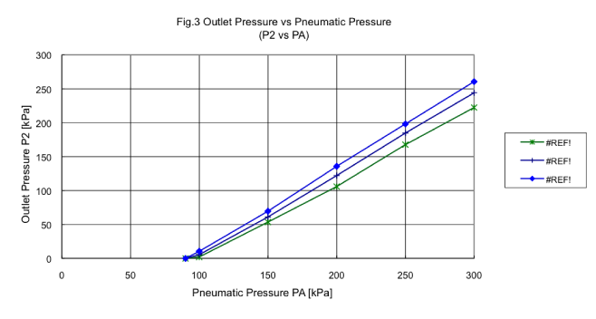
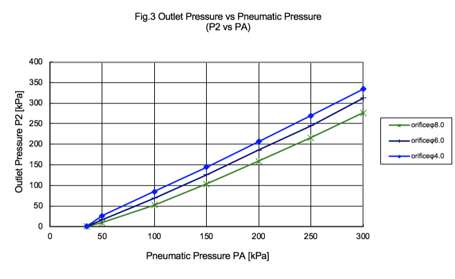
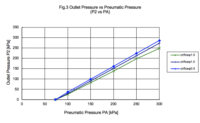
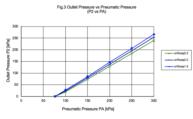
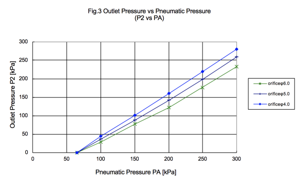
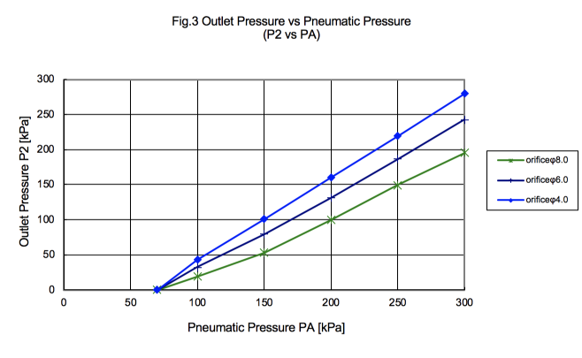
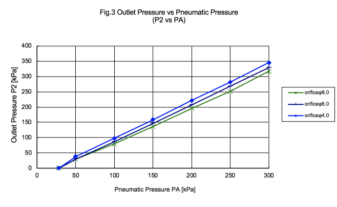
Fig. 3 Outlet Pressure vs Pneumatic Pressure
Measurement Method :
Inlet Pressure P1=500 [kPa]
-
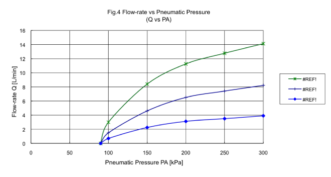
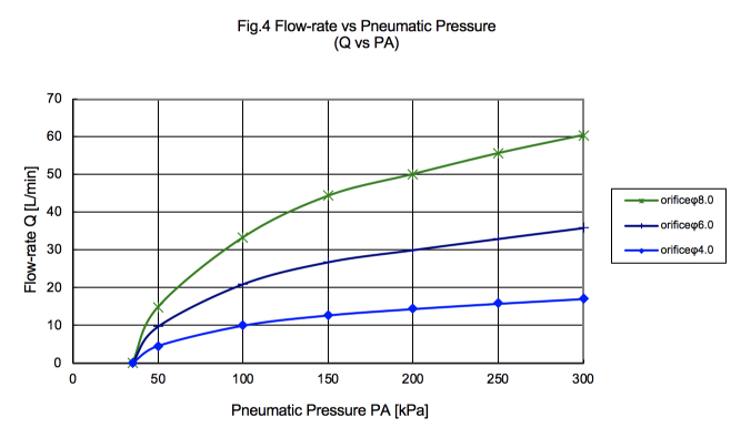
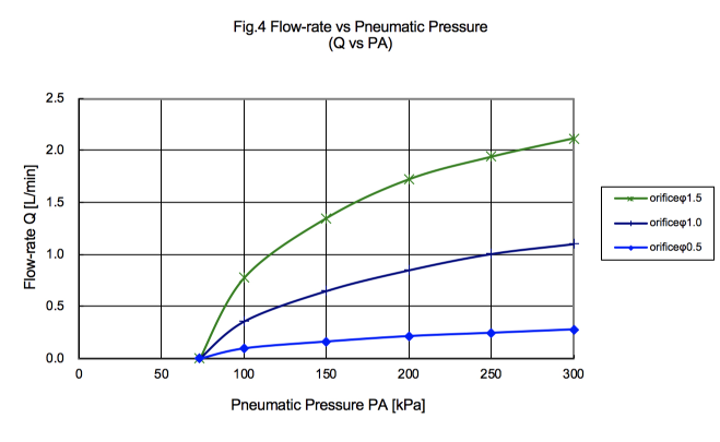
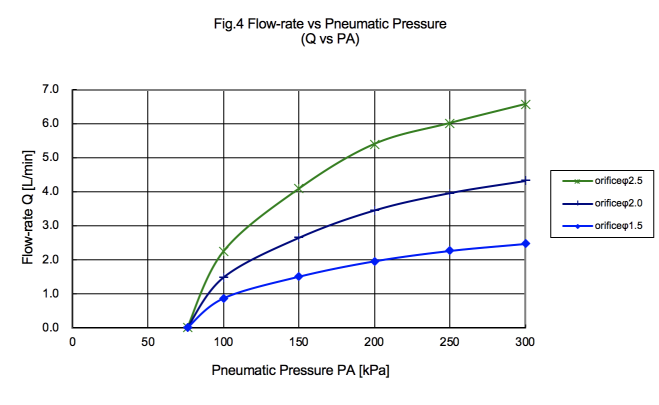
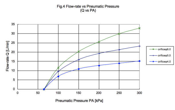
Fig. 4 Flow-rate vs Pneumatic Pressure
Measurement Method :
Inlet Pressure P1=500 [kPa]
-
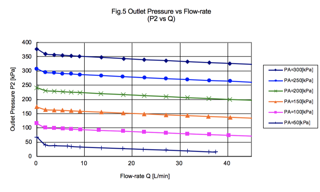
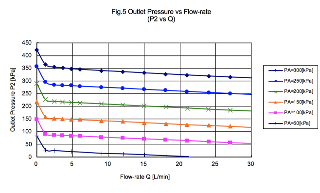
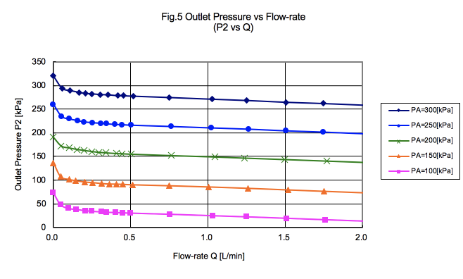
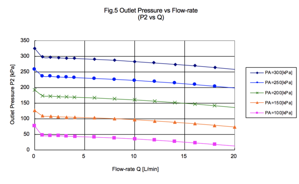
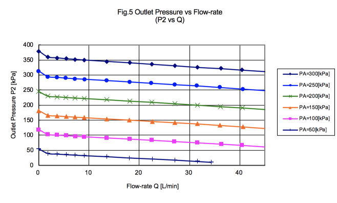
Fig. 5 Outlet Pressure vs Flow-rate
Measurement Method :
Inlet Pressure P1=500 [kPa]
HICV-045CB*-131 (Connection Size : 6.35×9.53, 8×10)
-
Fig. 1 Outlet Pressure vs Inlet Pressure
Measurement Method :
2.5mm fixed orifice is installed down stream of test unit.
-
Fig. 2 Flow-rate vs Inlet Pressure
Measurement Method :
2.5mm fixed orifice is installed down stream of test unit.
-
Fig. 3 Outlet Pressure vs Pneumatic Pressure
Measurement Method :
Inlet Pressure P1=500 [kPa]
-
Fig. 4 Flow-rate vs Pneumatic Pressure
Measurement Method :
Inlet Pressure P1=500 [kPa]
-
Fig. 5 Outlet Pressure vs Flow-rate
Measurement Method :
Inlet Pressure P1=500 [kPa]
Model Selection Table
Specifications
| Orifice Size [mm] |
φ12 equivalency |
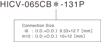
| Connection Size [mm] |
9.53×12.7 |
10×12 |
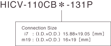
15.88×19.05 |
16×19 |
Recommended Flow Range
[L/min]H2O |
5 ~ 10 |
| Media Pressure |
Inlet
Pressure
[MPa] |
0 ~ 0.5 |
Outlet
Pressure
[MPa] |
0 ~ 0.5 |
| Media |
DI water / Corrosive fluid (Do not use fluids which can attack wetted materials) |
| Media Temperature [℃] |
10 ~ 90 |
| Ambient Temperature [℃] |
0 ~ 40 |
| Pneumatic Pressure [MPa] |
0.1 ~ 0.3 |
| Wetted Material |
Corrosion-resistant plastic |
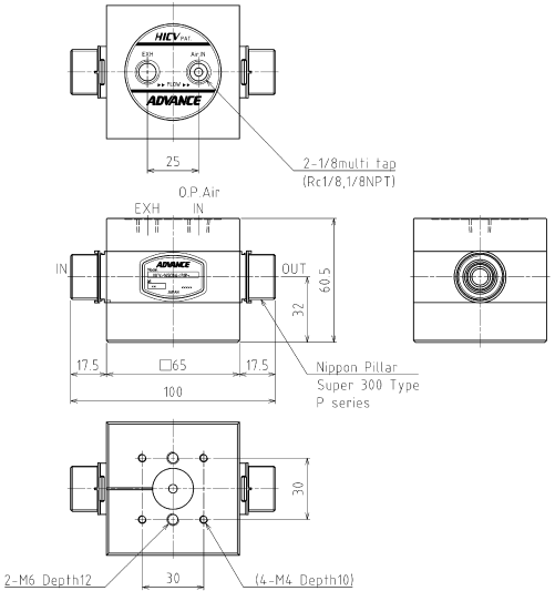
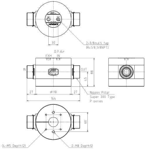
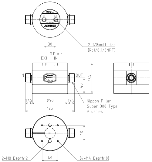
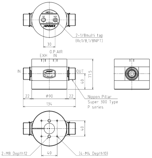
Dimensional Drawing(unit : mm)
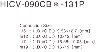
HICV-090CB*-131P (Connection Size : 9.53×12.7, 10×12)
HICV-090CB*-131P (Connection Size : 15.88×19.05, 16×19)
HICV-090CB*-131P (Connection Size : 9.53×12.7, 10×12)
-
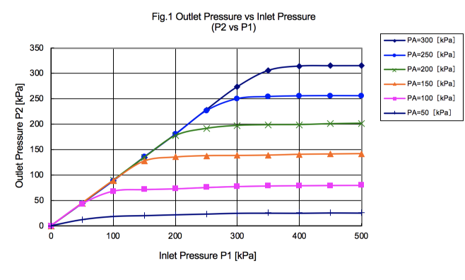
Fig. 1 Outlet Pressure vs Inlet Pressure
Measurement Method :
5.0mm fixed orifice is installed down stream of test unit.
-
Fig. 2 Flow-rate vs Inlet Pressure
Measurement Method :
5.0mm fixed orifice is installed down stream of test unit.
-
Fig. 3 Outlet Pressure vs Pneumatic Pressure
Measurement Method :
Inlet Pressure P1=500 [kPa]
-
Fig. 4 Flow-rate vs Pneumatic Pressure
Measurement Method :
Inlet Pressure P1=500 [kPa]
-
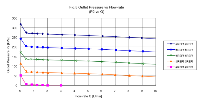
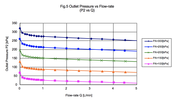
Fig. 5 Outlet Pressure vs Flow-rate
Measurement Method :
Inlet Pressure P1=500 [kPa]
HICV-090CB*-131P (Connection Size : 15.88×19.05, 16×19)
-
Fig. 1 Outlet Pressure vs Inlet Pressure
Measurement Method :
6.0mm fixed orifice is installed down stream of test unit.
-
Fig. 2 Flow-rate vs Inlet Pressure
Measurement Method :
6.0mm fixed orifice is installed down stream of test unit.
-
Fig. 3 Outlet Pressure vs Pneumatic Pressure
Measurement Method :
Inlet Pressure P1=500 [kPa]
-
Fig. 4 Flow-rate vs Pneumatic Pressure
Measurement Method :
Inlet Pressure P1=500 [kPa]
-
Fig. 5 Outlet Pressure vs Flow-rate
Measurement Method :
Inlet Pressure P1=500 [kPa]
Model Selection Table
Specifications
| Orifice Size [mm] |
φ24.5 equivalency |
| Connection Size [mm] |
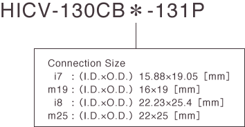
15.88×19.05 |
16×19 |
22.23×25.4 |
22×25 |
Recommended Flow Range
[L/min]H2O |
10 ~ 45 |
| Media Pressure |
Inlet
Pressure
[MPa] |
0 ~ 0.5 |
Outlet
Pressure
[MPa] |
0 ~ 0.5 |
| Media |
DI water / Corrosive fluid (Do not use fluids which can attack wetted materials) |
| Media Temperature [℃] |
10 ~ 90 |
| Ambient Temperature [℃] |
0 ~ 40 |
| Pneumatic Pressure [MPa] |
0.1 ~ 0.3 |
| Wetted Material |
Corrosion-resistant plastic |
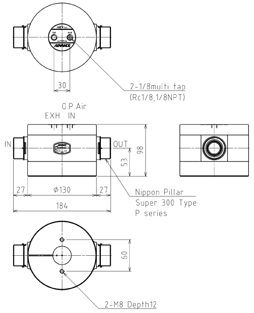
Dimensional Drawing(unit : mm)
HICV-130CB*-131P (Connection Size : 15.88×19.05, 16×19)
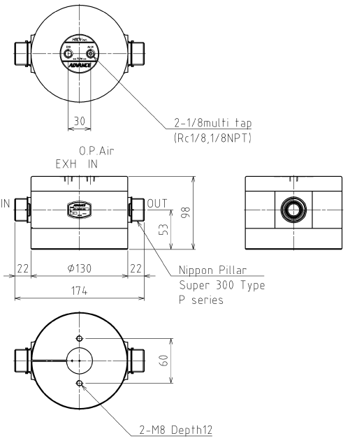
HICV-130CB*-131P (Connection Size : 22.23×25.4, 22×25)
HICV-130CB*-131P (Connection Size : 15.88×19.05, 16×19)
-
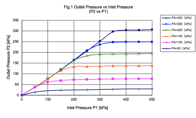
Fig. 1 Outlet Pressure vs Inlet Pressure
Measurement Method :
8.0mm fixed orifice is installed down stream of test unit.
-
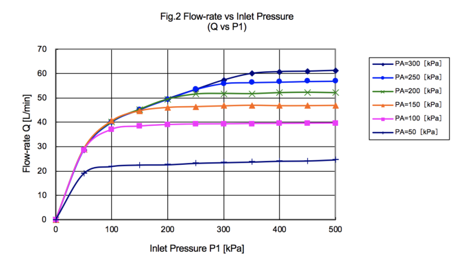
Fig. 2 Flow-rate vs Inlet Pressure
Measurement Method :
8.0mm fixed orifice is installed down stream of test unit.
-
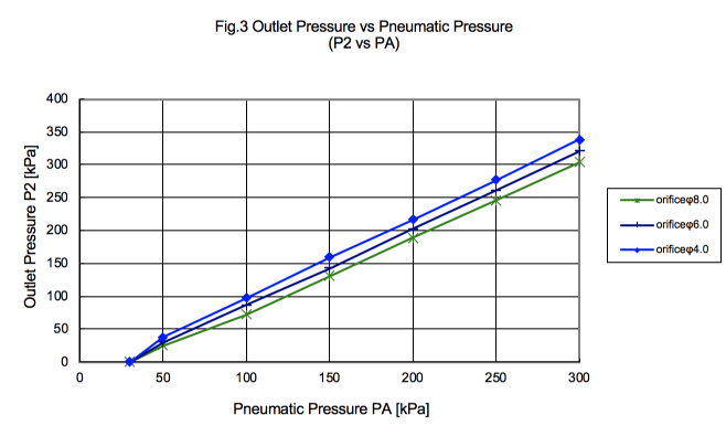
Fig. 3 Outlet Pressure vs Pneumatic Pressure
Measurement Method :
Inlet Pressure P1=500 [kPa]
-
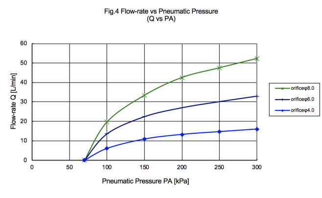
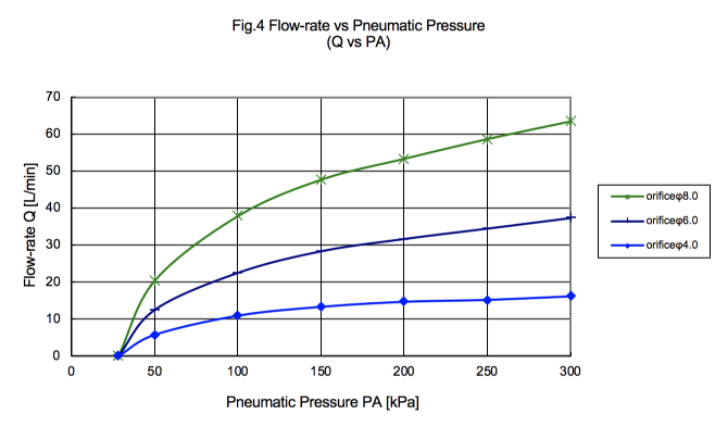
Fig. 4 Flow-rate vs Pneumatic Pressure
Measurement Method :
Inlet Pressure P1=500 [kPa]

-
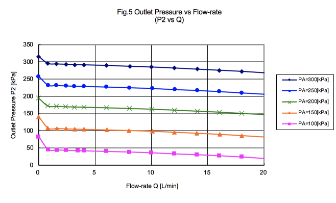
Fig. 5 Outlet Pressure vs Flow-rate
Measurement Method :
Inlet Pressure P1=500 [kPa]
HICV-130CB*-131P (Connection Size : 22.23×25.4, 22×25)
-
Fig. 1 Outlet Pressure vs Inlet Pressure
Measurement Method :
8.0mm fixed orifice is installed down stream of test unit.
-
Fig. 2 Flow-rate vs Inlet Pressure
Measurement Method :
8.0mm fixed orifice is installed down stream of test unit.
-
Fig. 3 Outlet Pressure vs Pneumatic Pressure
Measurement Method :
Inlet Pressure P1=500 [kPa]
-
Fig. 4 Flow-rate vs Pneumatic Pressure
Measurement Method :
Inlet Pressure P1=500 [kPa]
-
Fig. 5 Outlet Pressure vs Flow-rate
Measurement Method :
Inlet Pressure P1=500 [kPa]